Carbon Dioxide Containment Risk Assessment: The current state-of-the-art
The end of 2020 marked two milestones for Risktec – ten years since our first ever Carbon Capture and Storage (CCS) risk assessment project, and the end of the three year European funded “DETECT” research project.
Together with Shell, Heriot-Watt University and RWTH Aachen University, Risktec has been working as part of the Accelerating Carbon Technologies (ACT) funded DETECT research project to consider the integrity of underground carbon dioxide (CO2) storage sites. The purpose was to enable the risks of CO2 leakage to be managed to prevent any potential adverse effects on the surrounding environment and people. Further information about the project and access to the deliverables is available at https://risktec.tuv.com/eu_detect/.
To date, Risktec has collaborated with ten worldwide CCS projects and over this period we have developed, in conjunction with experts in the industry, a suite of tools and methods to efficiently identify, assess and demonstrate effective management of threats to geological CO2 containment.
CONTAINMENT RISK ASSESSMENT
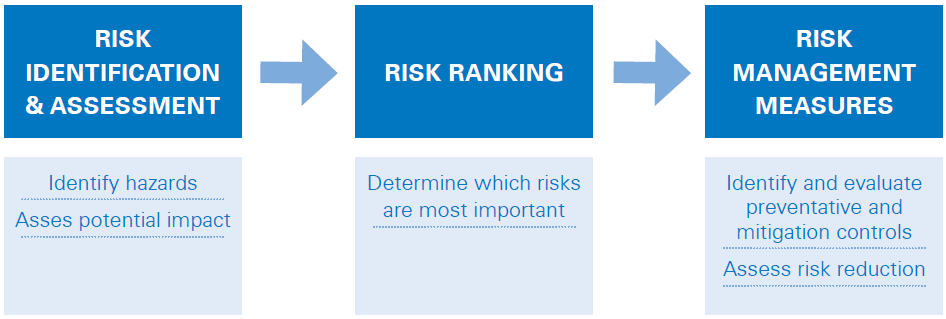
CCS projects typically develop a Containment Risk Assessment (CRA) as part of the permit application process. Akin to a safety case in other major hazard industries, the CRA describes the proposed storage site, identifies the significant risks and demonstrates that they are being managed effectively.
Central to the CRA is bowtie analysis. This diagrammatical approach is well suited to presenting the causes and consequences of loss of CO2 containment and describing and evaluating the prevention and mitigation measures available to manage the risk – a key step in the CRA process (Figure 1).
Whilst bowtie analysis has been used for many years in the oil and gas industry, to the point that standard approaches are well established (Ref. 2), its application to the emerging CCS industry requires some adaptation to accommodate the novel features of geological CO2 storage in contrast to traditional process safety risks of loss of containment.
BOWTIE ADAPTATION FOR SUBSURFACE CO2 STORAGE
Process safety bowties often present separate causal branches for each mechanism that can bring about loss of containment, e.g. corrosion, overpressure, impact, etc. Analogous mechanisms exist with geological CO2 storage, (e.g. corrosive effects of acidic CO2 on sealing formations), and these can equally be considered in bowtie branches. However, an alternative and effective approach is to structure subsurface CO2 bowtie diagrams with each branch depicting a defined leak path out of the storage site.
Engineered barriers feature in both types of bowtie, as do operational strategies (such as setting limits on maximum CO2 injection pressures and rates). However, geological features such as sealing formations, bounding faults, structural dips and permeable storage formations also play a significant role in preventing and mitigating loss of CO2 containment and appear on both sides of the bowtie diagram.
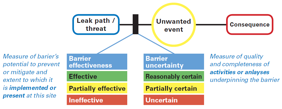
The natural, passive nature of these barriers means their performance is more difficult to quantify, and a useful additional aspect of the barrier strategy for CO2 storage is to determine the level of uncertainty associated with each barrier’s effectiveness (Figure 2). At the early stages of a CCS project, levels of uncertainty are high; as the project progresses and further data are gathered and analyses undertaken, this uncertainty diminishes. The bowtie analysis helps direct the project to the most critical barriers, on which there is most reliance for maintaining containment, and therefore on areas where further work is required to reduce uncertainty around the barriers’ quality and efficacy.
QUANTIFICATION OF RISK
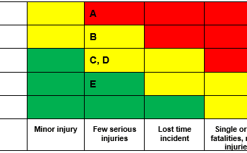
Two areas of concern that are frequently raised with regard to the use of bowtie analysis are that they are subjective (in that the acceptance of risk relies on judgement and opinions rather than absolute values) and that it can be difficult to identify the most critical sequences. The latter point can be partially addressed by considering the frequency with which threats may occur and by also considering the magnitude of consequences (e.g. the quantity of CO2 that might be released and its duration). There is still, however, a role for some form of numerical risk assessment within the CRA, alongside the bowtie diagrams.
Projects will perform detailed numerical simulations of CO2 migration over time within a reservoir; these simulations can take time to set-up and run, and although they give an indication of where CO2 may reach, they may not necessarily give information in a format that is amenable to quantifying risk.
To meet the requirements of providing useful risk metrics, in a practical time frame, two methods have been pioneered for use within CCS CRA.
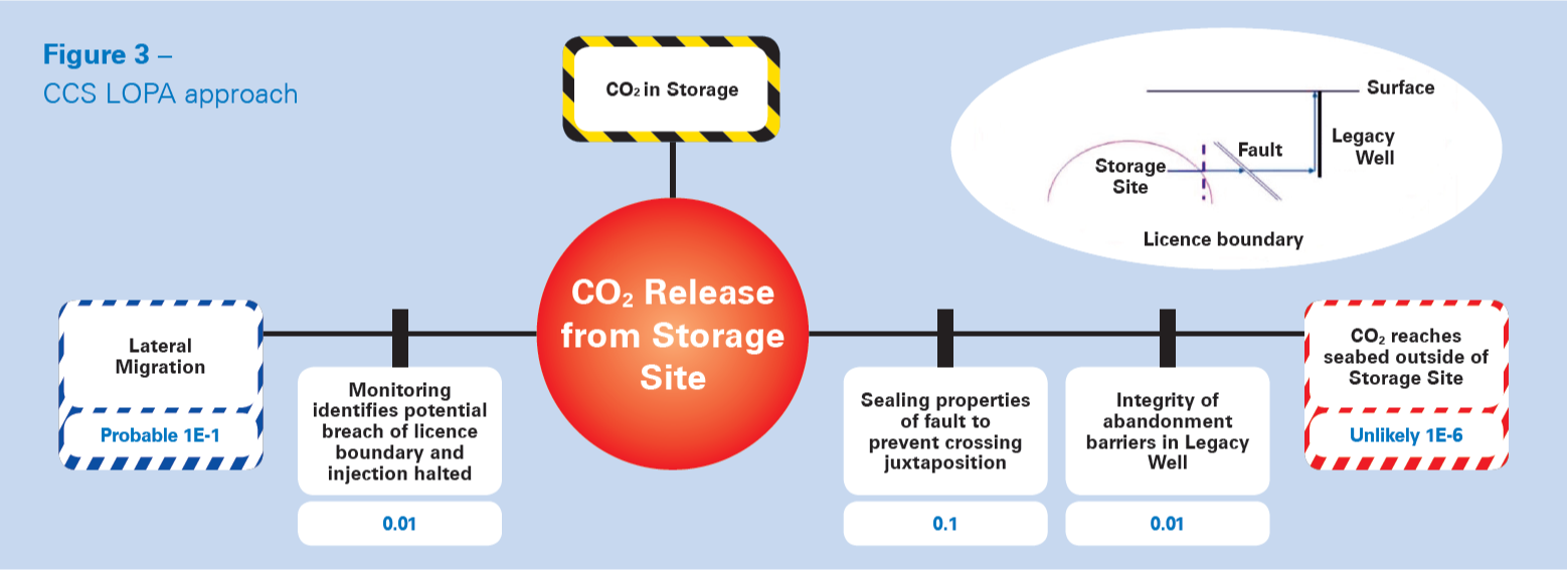
The first is a simplified Layers Of Protection Analysis (LOPA) approach, which builds upon the information collected during the bowtie analysis. LOPA is widely used in the process industries to provide an order of magnitude numerical estimation of risk, by considering the frequency of scenarios occurring and the risk reduction provided by protection layers (barriers). By identifying leak paths of concern and the barriers to prevent or mitigate them, it is possible to develop a ‘CCS LOPA’ as illustrated in Figure 3. All of the sequences considered can be plotted on a risk matrix to give an indication of the overall level of risk and the dominant sequences. The uncertainty information collected during the bowtie analysis can also be used to prioritise sensitivity studies.
The second approach is more suited towards quantitative analysis of legacy well release paths, which are generally accepted in the industry to be a dominant risk. Well-specific bowtie diagrams identify the barriers (e.g. abandonment plugs) that are being relied on to maintain CO2 containment. Considering the physical properties of each barrier (e.g. permeability, area, length, etc.) and the likelihood that a barrier may fail, it is possible to develop event trees to calculate the probability that leak rates will occur, and identify the most significant scenarios and barriers.
Both approaches are highly reliant on the judgements made in assigning numerical values (for which there is little data) and hence whilst they have the appearance of accuracy and certainty, the quantitative risk evaluation should be used with caution, particularly if absolute rather than comparative values are used as the basis for decision making.
CONCLUSION
It is important that a CRA presents information to allow stakeholders to make informed judgements about the nature and acceptability of risks posed by CCS projects. As different stakeholders will have different requirements, a range of approaches may be required; and the choice of strategy should take into account the quality of available information and the complexity of the situation. Nevertheless, established risk assessment techniques can be successfully adapted and applied to geological CO2 storage.
References
1. Implementation of Directive 2009/31/EC on the Geological Storage of Carbon Dioxide, European Commission Guidance Document 1 CO2 Storage Life Cycle Risk Management Framework, ISBN-13978-92-79-19833-5, 2011.
2. Center for Chemical Process Safety of the American Institute of Chemical Engineers, in association with the Energy Institute. Bowties in Risk Management, a Concept Book for Process Safety, ISBN 978-1-119-49039-5, 2018.