Materials failure investigation – Two critical techniques for a successful investigation
A thorough materials failure investigation is a key element of the overall root cause analysis following the failure of an industrial component. Determining the failure mechanism by examining the fracture surfaces and sections taken through those surfaces, enables recommendations to prevent recurrence of similar incidents. So what are these two examination techniques looking for?
A BRIEF INTRODUCTION TO FAILURE INVERSTIGATIONS
Failures of components in industrial applications can lead to unexpected downtime. In such circumstances, the cost of lost manufacturing can far outweigh the costs of the repair. Planned preventative maintenance (PPM) programmes can help reduce the number of components failing. However, PPM is only effective if the maintenance is aimed at controlling known degradation mechanisms. It is essential therefore, where unexpected failures occur, to investigate the failure mechanisms. Only through an understanding of these can PPM be optimised, or component designs improved, to minimise the risk of the failure occurring again.
A failure investigation is the process of determining the failure mechanism. This is not the same as a root cause analysis of the failure (RCA). The failure investigation is just one part of the RCA. Once the failure mechanism has been identified, the RCA must then be completed to understand why that failure occurred.
A full RCA can take many months and tie up a lot of resources, so often just a partial RCA is completed that involves a failure investigation followed by an engineering review.
How to carry out a failure investigation is a huge topic and the subject of many books, papers, training courses and seminars. This article provides a short overview of two key techniques that form a part of many investigations, namely:
- Examination of fracture surfaces.
- Examination of sections taken through the fracture surfaces, embedded cracks or areas of damage.
EXAMINATION OF FRACTURE SURFACES
There are many features on a fracture surface to help identify the cracking mechanism. The fracture surface will be assessed visually, with magnification aids, and potentially at very high magnification in a Scanning Electron Microscope (SEM).
Examples of the surface features associated with different types of cracks include:
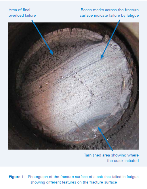
- Fatigue cracks tend to be flat with curved beach marks when examined visually (see Figure 1). At higher magnification in an SEM it may also be possible to determine striations, i.e. microscopic marks showing the incremental advance of the crack with each fatigue cycle.
- Ductile overload failures tend to be dull and show microvoid dimples when viewed in the SEM.
- Brittle overload failures tend to show more crystalline, shiny surfaces when viewed visually, and either cleavage facets (most typical) or intergranular facets when viewed in the SEM.
- Creep cracks tend to show fine but deep voids when viewed in the SEM, assuming there has been time for a thermal oxide to grow on the surface.
- Cracks initiating from a manufacturing defect may show atypical features in the fracture surface, for example there may be a significant amount of casting porosity in the middle of a flat fatigue crack.
- Corrosion induced cracks may show corrosion pits near the crackinitiation point.
Where cracks have grown to such an extent that a component is separated into multiple pieces it is easy to examine the fracture surfaces. Where a crack is still embedded within a component then a decision has to be made whether to break the crack open or not. Breaking the crack open allows a detailed examination of the fracture surface, but may lose detail of the embedded crack tip in crosssection.
Quite often, both sides of a fracture surface will contain valuable information about the failure mechanism. However, there are occasions where one side of a fracture surface will provide much more useful information than the other. Ideally, therefore, an examination of both fracture surfaces should be completed.
Oxide or corrosion products may obscure details of the fracture surface. However, these contaminants or scales on a fracture surface may contain important information about the cracking mechanism. The chemical composition of contaminants can be measured using Energy Dispersive X-ray Spectroscopy (EDS) in the SEM and may indicate a particular form of corrosion has been occurring. There are also a number of techniques that can be employed to gently clean fracture surfaces, from ultrasonic cleaning with solvents to chemical stripping to dissolve tenacious oxide scales. Fracture surfaces are therefore typically examined as-received and after cleaning.
It is very easy for additional damage to occur to fracture surfaces after the initial failure, especially when there is a requirement to get the equipment back into service quickly. Ideally, fracture surfaces should be protected with soft padding as soon as possible after the failure to ensure that laboratory work is only completed on the damage caused during the failure. Plastic bubble wrap is ideal since it provides good protection and does not transfer any fibres, dust or chemical contaminants onto the surfaces; all of which can hamper a microscopic examination.
EXAMINATION OF SECTIONS TAKEN THROUGH THE FRACTURE SURFACES, EMBEDDED CRACKS OR AREAS OF DAMAGE
A section through a failed component can reveal the interaction of any cracks or damage with the underlying microstructure of the material. The sections that are cut have to be polished to a mirror finish (typically one micrometre) and then chemically etched to reveal the microstructure. The sections tend to be examined using optical microscopy both in the as-polished and etched condition, as the etching can sometimes obscure features such as fine porosity or very small secondary cracks.
The sections can also be viewed in the SEM which allows electron imaging at higher magnifications (up to 20,000X) and backscattered imaging to give contrast based on material chemistry and atomic mass, EDS mapping to show elemental variation within a material, and EDS semi-quantitative chemical composition measurements to be made.
There are many features on cross sections that can provide valuable insight into failure mechanisms. Examples include:
- Secondary cracks showing any locations where there is a big driver for crack initiation.
- Chemical or corrosion pitting along surfaces where cracks have initiated.
- Metallurgical defects that indicate manufacturing non-conformance, such as incorrect microstructure showing that a component may have received an incorrect heat treatment, leading to weakening of the material.
- Degradation of microstructure in service, for example coarsening or dissolution of precipitates in precipitation strengthened materials, leading to weakening of the material.
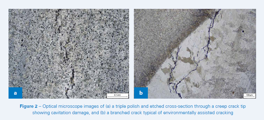
- Creep cavitation forming at grain boundaries on components exposed to stress at high service temperatures (see Figure 2a).
- Branching of cracks (see Figure 2b) where environmental attack is a significant factor in the failure, e.g. corrosion fatigue or stress corrosion cracking.
- Oxide or corrosion products within cracks, whereby EDS chemical analysis would provide insight into what form of corrosion had been occurring, or where scale thickness could provide information about the temperature a component had been exposed to.
Polished micro-sections also allow accurate hardness and micro-hardness measurements to be made at different positions through the wall of a component. Even where the microstructure looks acceptable this may provide evidence of inferior mechanical properties at certain locations within the component.
USING THE FAILURE MECHANISM TO INFROM RECOMMENDATIONS
Once the mechanism has been established, an RCA is often completed to determine why that failure mechanism specifically would have been active for the component. A full RCA is complex and can take many months as every potential method of inducing the failure mechanism is investigated and tested. However, it is often sufficient to carry out a partial RCA where the failure investigation is followed by an engineering review, and this can provide valuable recommendations for mitigating the risks of further failures.
Consider two examples. First, if a crack had grown from a manufacturing defect, then the engineering review could easily attribute the failure to the manufacturing defect and look at improving quality control during manufacture. Second, if a component had failed in creep, then there could be multiple potential reasons to explain why the creep was occurring, requiring a more complex engineering assessment:
- Was the component operating at a higher temperature than it should have been?
- Were the stresses in the component higher than they should have been?
- Was the original material data used for the design reliable, i.e. were the data extrapolated too far?
- Was there an interplay with other damage mechanisms?
- Was the material of the correct, specified grade and heat treatment condition?
To provide useful and pragmatic recommendations requires an in-depth understanding of the component and equipment operation, a comprehensive knowledge of engineering, a good understanding of the materials, and often an impartial consideration of the human factors that may have been involved. This is often best achieved by bringing together a team of people, such as a site operator or engineer responsible for the equipment and who knows what people were involved, an engineering specialist and a materials specialist.
CONCLUSION
Failures of components in industrial applications can result in significant process safety risks, costly damage, loss of plant availability and negative publicity and prosecution. To prevent recurrence a failure investigation is required to determine the failure mechanism – a key input to the root cause analysis.
Two critical techniques that form a part of many investigations involve the examination of fracture surfaces and the examination of sections taken through the fracture surfaces, embedded cracks or areas of damage.
A suitably qualified and experienced team will use the failure investigation to generate useful and pragmatic recommendations for the plant.
References:
- Safety of pressure systems. Pressure Systems Safety Regulations 2000. Approved Code of Practice and guidance on Regulations. UK HSE. L122, 2nd Edition, 2014.