Boiler Tube Life Management – Critical issues for biomass and energy-from-waste plant
Boiler tube leaks can lead to unscheduled repairs on industrial boilers. When this occurs, the cost penalties of lost production can far outweigh the cost of the repairs. Biomass and energy-from-waste boilers are a particular challenge due to their high temperatures and corrosive atmospheres. It is vital, therefore, to have a maintenance strategy that minimises the number of tube leaks, while taking account of the site’s risk appetite and other influences.
BOILER TUBE LEAKS
Boiler tube leaks can occur due to:
- Damage to the internal surface of the tubes
- Damage to the external surface of the tubes
- Degradation of the microstructure and mechanical properties of the tubes over time
Careful control and monitoring of water chemistry and effective off-load preservation can prevent failure mechanisms occurring at the internal surface of the tubes. The correct choice of materials and good plant operation can prevent failures due to degradation of the microstructure and mechanical properties.
However, controlling failure mechanisms that attack the external surface of tubes is much more difficult, especially in biomass and energy-from-waste boilers which generate high temperatures and corrosive atmospheres. In these environments, the external surface of the boiler tubes will inevitably be attacked, and the key to minimising leaks is choosing the optimum time to replace tubes during scheduled maintenance outages, as well as the most cost-effective material to use in a given environment.
BOILER SURVERYS
Boiler surveys during scheduled maintenance outages provide a regular opportunity for assessing the condition of boiler tubes. These surveys are best conducted using a combination of visual and non-destructive inspection techniques. Ultimately, the aim is to use non-destructive techniques to measure metal loss and then to calculate how fast boiler tubes are thinning.
It is essential to know where to take the measurements and how many different measurements to take. Drawing on a good working knowledge of a boiler (for example, temperatures, pressures, fuel type and firing conditions) it is possible to create risk maps that show which failure mechanisms are likely to be active in different parts of the boiler.
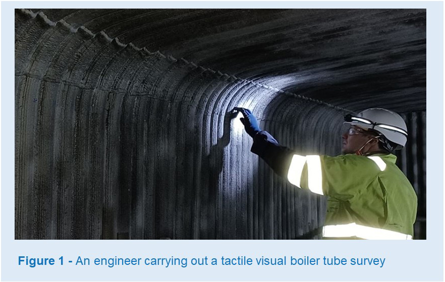
Risk maps can help prioritise which areas of a boiler to inspect. For some boiler designs, the original equipment manufacturer (OEM) will supply measurement positions which may make inspection simpler. However, these make the assumption that the boiler will behave as per the nominal design conditions, which is seldom the case. Therefore the first step to successfully surveying a boiler is to complete a tactile visual inspection (see Figure 1).
VISUAL INSPECTIONS
Tactile visual inspections allow a detailed examination of the tubes. This involves physically entering the boiler and closely checking each of the accessible tubes for evidence of degradation. Thick deposits can form over heat exchanger surfaces in a boiler due to the non-combustible components of the fuel and, as a result, defective tube surfaces can be hidden beneath these deposits.
It is vitally important to clean a boiler thoroughly prior to inspection, ideally removing ash deposits but leaving any protective scale on the tubes. The quality of the clean can greatly affect the quality of the subsequent inspections and hence can directly influence the inspectors’ ability to identify tubes that are likely to leak during the next operating interval, or require planned replacement at a future outage. Once the tube surfaces are clean, inspectors require adequate access to inspect all the tubes closely. In some boiler designs, complex scaffolds are required to provide suitable access throughout.
Where tubes are nestled into closely packed tube banks, only the outermost tubes on each tube bank can normally be accessed, and these are usually taken as being representative of the other tubes within the tube bank. The tactile aspect of the inspection reveals the texture of the surface of the metal (e.g. smooth, scalloped or pitted) and can help determine what additional inspections should be completed. Additionally, even after cleaning, some of the tubes will be covered in scale and this scale will need to be scraped off during the tactile visual survey to reveal the metal underneath. The nature of the scale as it is scraped off (e.g. flaky, banded, powdery or moist) can provide information about the aggressiveness of the degradation.
BOILER TUBE DEGREDATION
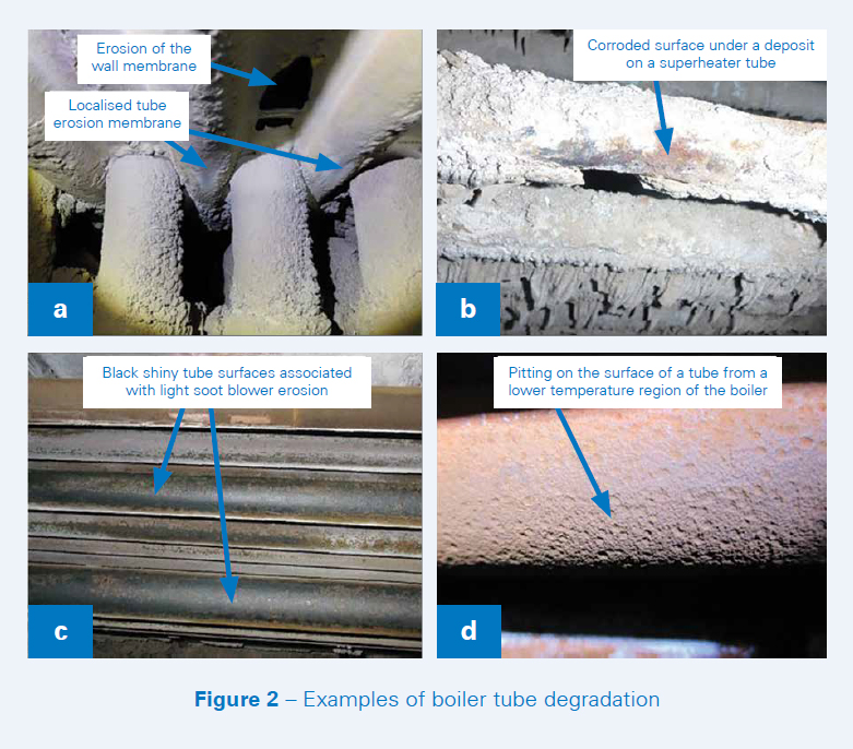
Examples of boiler tube degradation can be seen in Figure 2. Some forms of metal loss, for example fly ash erosion, can be extremely localised, especially when high gas flow rates occur around blockages. Localised tube damage such as this can be missed if just inspecting a set of predefined positions within a boiler.
Soot blowers can be used to clean away deposits that build up and reduce the efficiency of heat transfer surfaces. Tubes that are closer to the path of the soot blowers tend to clean quickly whereas tubes that are further away take longer to clean. This phenomenon can lead to soot blower erosion of the tubes, and there is a risk that tubes closer to the path of the soot blowers will degrade faster than tubes further away.
Attachment welds onto boiler tubes can impede hot gas flow around the tubes and can act as constraints as boilers expand and contract, potentially leading to low-cycle fatigue stresses. Therefore, such attachments should also be closely monitored.
Where corrosion is occurring, the rate of degradation can be a function of the gaseous atmosphere in the boiler (temperature, pressure and composition) and the chemistry of any deposits on the surface of the tubes. Removing and assessing samples of deposit from tubes can provide valuable insight into corrosion mechanisms.
The tactile visual survey should identify a list of tubes where thickness measurements should be taken using non-destructive techniques. This list of specific issues identified during the outage can be combined with any other routine inspection points or those recommended by the OEM to enable the condition of specific locations to be tracked over time. Local surface preparation of the inspection points will be required in order for nondestructive testing to be effective and repeatable.
Where the visual inspection has shown that the external surfaces of the tubes are pitting, consideration should be given to removing a sample of tube at least one metre in length from a critical area of the boiler. Tube thicknesses on this sample of tube should be measured using the same non-destructive technique as employed on the rest of the boiler. In addition, metallographic techniques should be used to measure the wall thickness associated with the deeper pits. Any difference in thickness measurements can be used to assess the risk of leaks occurring where pitting corrosion is found in the boiler.
TUBE THICKNESS MEASUREMENTS
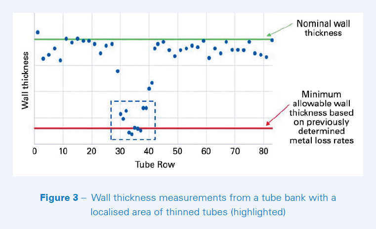
An example of tube thickness measurements for an industrial boiler showing a localised area of thinned tubes is shown in Figure 3. As well as identifying areas of thinned tubes, tube thickness measurements can be used to calculate tube wastage rates. Tube wastage rates can be used to assess whether a tube is likely to leak or not within the next operating interval, and plan future replacements or other remedial work.
In simple terms, the tube wastage rate is the metal loss divided by the number of hours the tube has been in service. However, this assumes a linear relationship, which may not always be the case. For instance, erosion may only occur when a deposit has built up in a particular position and hence may only be occurring for short periods between soot blower cleaning; or, where hot corrosion is occurring, the rate of metal loss may increase with time.
Engineering judgement, based on a knowledge of how a boiler is operating, is therefore essential to be able to accurately extrapolate tube wastage rates to give a tube life estimate. The more data that can be collected over time to confirm tube wastage rates, the more accurate the extrapolations to estimate tube life will be. For this reason, in biomass and energy-from waste-boilers it is important to carry out boiler tube surveys regularly, during scheduled maintenance outages.
When thickness drops below a critical level, tubes will need to be replaced if unscheduled tube leaks are to be avoided. Where degradation is localised, only a limited number of tubes may need to be replaced or in-situ remedial work (e.g. weld build up) may be possible. When doing so, extreme care must be taken to ensure that service tubes to be welded have acceptable wall thickness and are properly cleaned prior to welding. Expert welding advice should be sought and followed, and all new welds should be appropriately tested for quality.
Traditionally, X-ray techniques have been used to inspect new welds on boiler tubes, but phased array ultrasonic techniques are now available which can significantly reduce cost, time and disruption. If there is widespread boiler tube wastage across the tubes in a tube bank, the whole tube bank will need to be replaced – see Figure 4. This can result in large sections of the boiler casing and/or membrane wall having to be cut away. Where frequent tube replacements have to be made, it can be beneficial to redesign access into the boiler to better facilitate maintenance activities.
TUBE REPLACEMENT
If the same material is used when replacing boiler tubes, it is likely that the tubes will need to be replaced again after a similar service interval if other factors (e.g. fuel characteristics) remain the same. However, if degradation mechanisms are well understood, it may be possible to find alternative material systems or designs that will increase service intervals between tube replacements.
A range of different alloys, weld overlay and coating systems, and techniques using shields or baffles, exist for increasing boiler tube service intervals, but these usually come at an increased cost. To avoid increasing long-term maintenance costs, a cost-benefit analysis should be completed whenever making fundamental changes to a boiler design, such as changing the materials of a system, because each boiler has a unique set of conditions.
If hot corrosion is found to be a problem, the best approach for selecting an optimum material may be to carry out a ‘rainbow test’ of alternative material systems directly in the boiler where the corrosion is occurring. Where changes in material or design are required, more expensive, more resistant, material systems may only need to be used in a few select positions within the boiler.
CONCLUSION
Regular boiler tube surveys are essential for minimising unscheduled tube leaks in large industrial boilers, especially in biomass-fired and energy-fromwaste plant.
Surveys: To carry out a successful boiler tube survey, all accessible tubes need to be checked which, in some boiler designs, can require complex scaffolds. The surfaces of all tubes need to be cleaned prior to inspection.
Inspections: Tactile visual inspections, combined with routine inspection points and OEM recommended points, can be used to build a list of positions where non-destructive tube thickness measurements should be taken. Local surface preparation of the inspection points will be required in order for non-destructive testing to be effective and repeatable.
Tube measurements: Tube thickness measurements can be used to calculate tube wastage rates. Applying engineering judgement to these calculations can generate an estimate of tube life and the point at which tubes should be replaced.
Tube replacements: Where tube replacements need to be made, follow expert welding advice and quality check all new welds. If alternative systems are to be used to increase service intervals between tube replacements, conduct a cost-benefit analysis to find the optimum solution.